Self Balancing Robot
A two-wheeled, self-balancing robot created using an Arduino and a MPU6050 gyroscope.
Parts
- Arduino Uno Microcontroller
- MPU6050 Accelerometer and Gyroscope
- L298N Motor Driver
- 2 x 300 RPM motors with wheels, 9V
- 3 x \(1\,M\Omega\,\) 10 turn potentiometers
- 9V battery and barrel jack clip with switch
- 6 x AA batteries and barrel jack case with switch
- Assorted Wires
- Female header pins
- Proto boards
- Materials for a frame
Tools
- Soldering iron
- Screwdriver
- Drill and drill bits
Building
Please review the schematic below before proceeding to the build directions.

Directions
- Get a protoboard, and solder three potentiometers (for PID tuning) and a seven-pin header for the MPU6050 to it.
- Using fully stripped wires, connect VCC on the MPU6050 and one side of each trim pot together.
- Solder wires onto the protoboard for the trim pot outputs, the VCC line created in the previous step, and GND, SCL, SDA, and INT on the MPU6050.
- Attach the Arduino, protoboard, and L298N to the robot frame.
- Connect the Arduino to the wires on the protoboard, following the schematic.
- Using jumper wires, connect the Arduino to the L298N according to the schematic.
- Connect the L298N to the motors.
- Attach the battery cases to the robot frame. The 6 x AA case should be low to improve center of gravity.
- Connect the 9V battery to the Arduino and the 6 x AA batteries to the motor controller.
- Flash the firmware to the Arduino (see below).
- Turn on the motor switch, then the Arduino switch, wait for the MPU6050 to calibrate, and let the robot go!
- Tune PID constants as needed using the potentiometers to achieve stability. Adjust \(P\) until the robot oscillates back and forth with relative stability, then adjust \(I\) until the robot stops falling over, and finally adjust \(D\,\) to dampen the oscillations.


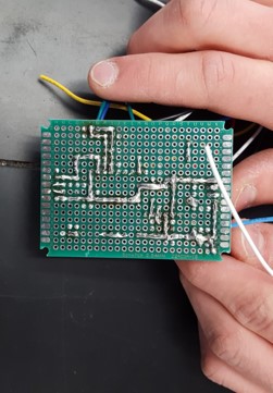
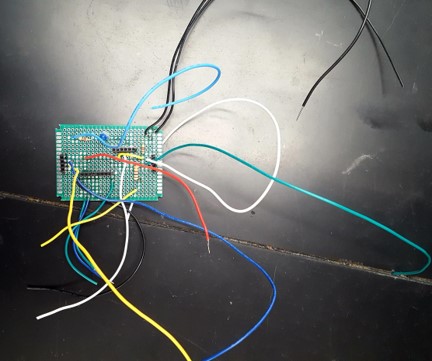
The completed protoboard, viewed from the top and bottom.
The Code
The code is all written in C++, and can be found here. At a high level, the code consists of two parts, a setup and a loop, than can be imagined to work like this:
void setup();
void loop();

void main()
{
    setup();

    for (;;)
        loop();
}
Inside the setup function, we perform several actions:
- Set up serial communication
- Initialize the I2C bus.
- Initialize the MPU6050 and set up its Digital Motion Processor (DMP), which gives us more accurate position data in simple Yaw/Pitch/Roll angles.
- Catch and report any errors along the way.
Then, we just to the loop. If anything failed in the setup, we blink an LED to signify our error, and do nothing. Otherwise, we perform the following actions:
- Loop until DMP data is ready, during which we:
- Compute PID and update motor powers.
- Read new PID constants from the trim pots.
- Blink our LED.
- Check for new DMP data to exit the loop.
- Now that our DMP data is ready (signified by an interrupt or check for new data), we reset our interrupt and make sure that we have received a packet from the DMP.
- Then, we make sure our DMP communication buffer has not overflowed, because then we would be working on stale data.
- Now, we read the latest DMP packet, and use it to compute a position quaternion.
- Using that quaternion, we compute gravity, and then Yaw/Pitch/Roll.
- We save the Roll data, as that tells us the robot’s angle from vertical, and loop again to update motor controls.